









































CNC Tool Geometry: Flutes, Angles & Cutting Edges
Learn how CNC tool geometry, including flutes, helix angles, rake angles, and cutting edges, affects machining accuracy, tool life, and performance.
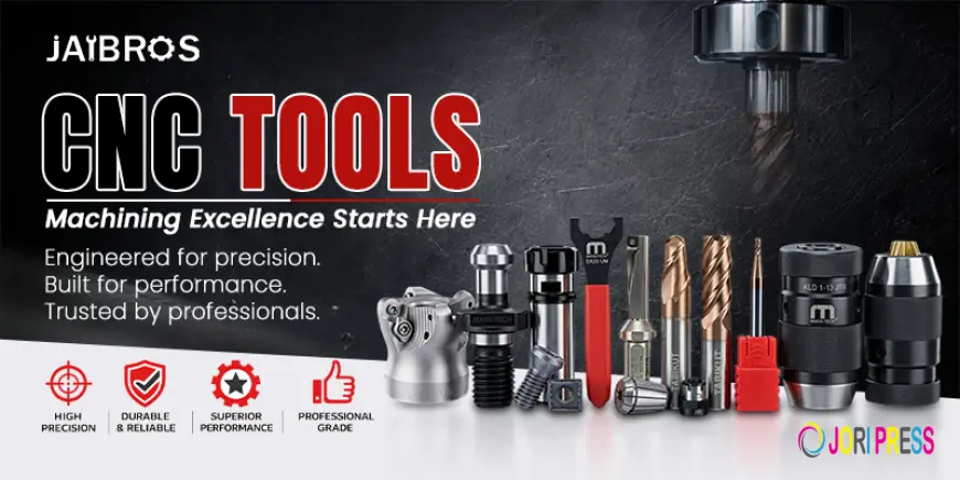
Understanding CNC Cutting Geometry for Better Machining Results
Choosing the right cutting tool is only one part of achieving accurate and efficient machining. The geometry of a cutting tool has a major effect on how material is removed, how heat is managed, and how long the tool lasts. Flutes, cutting angles, edge design, and other geometric features are carefully engineered for specific machining conditions.
Whether you work with aluminum, steel, stainless steel, plastics, or other materials, understanding cutting geometry can help you select the right option for your application. This guide explains the main elements of geometry and how they influence machining performance.
What Is CNC Tool Geometry?
CNC tool geometry refers to the physical shape and design of a cutting tool, including its flutes, rake angle, clearance angle, cutting edges, helix angle, and tip configuration. Each feature has a specific purpose and affects cutting performance.
Different applications require different geometries. For example, a tool designed for aluminum may have a different flute configuration from one intended for hardened steel. Similarly, drilling, milling, threading, and finishing operations require different cutting-edge designs.
Understanding these differences becomes particularly useful when working with different types of CNC machine, because machine capabilities, spindle speeds, workpiece materials, and machining operations can vary significantly.
Understanding Flutes and Their Purpose
Flutes are the grooves running along the body of a milling cutter or similar cutting tool. They create cutting edges while providing space for chips to move away from the cutting area.
The number of flutes is an important part of tool geometry. A two-flute cutter, for example, provides more space for chip evacuation, making it suitable for materials that generate larger chips. Tools with more flutes generally provide more cutting edges and can be useful when higher feed rates and better surface finishes are required.
However, simply choosing a higher flute count does not always produce better results. The correct number depends on the material, spindle speed, feed rate, depth of cut, and application.
For roughing operations, chip clearance may be more important, while finishing operations may benefit from additional cutting edges.
What Is Helix Angle?
The helix angle describes the angle formed by the cutting edge as it moves around the tool body. It influences chip formation, cutting forces, vibration, and surface finish.
A higher helix angle generally produces smoother cutting action and can reduce the impact of the cutting edge entering the workpiece. This can be beneficial for softer materials and finishing operations.
A lower helix angle can provide greater edge strength and may be suitable for tougher materials or applications where rigidity is important.
Selecting the correct geometry therefore requires balancing cutting efficiency with edge strength and workpiece requirements.
Rake Angle and Its Effect on Cutting
Rake angle is another important geometric feature. It determines how the cutting edge interacts with the material and influences the force required during cutting.
A positive rake angle can help reduce cutting forces and encourage smoother chip flow. This is often useful when machining softer materials such as aluminum.
A smaller or negative rake configuration can provide a stronger cutting edge and may be preferred for harder materials or demanding machining conditions.
The correct rake design depends on the material being machined and the desired balance between cutting efficiency and edge durability.
Clearance Angle and Cutting Performance
The clearance angle creates space between the tool's body and the machined surface. Without adequate clearance, the tool could rub against the workpiece rather than cutting efficiently.
Too little clearance can increase friction, heat, and wear. Excessive clearance, however, can weaken the cutting edge.
Manufacturers therefore design clearance angles carefully to provide enough space for smooth cutting while maintaining sufficient edge strength.
When selecting the best CNC tools for a particular operation, operators should consider geometry alongside material compatibility, coating, diameter, and machine parameters.
Cutting Edges and Edge Preparation
The cutting edge is the part of the tool that directly contacts and removes material. Its sharpness, shape, and preparation can significantly affect machining results.
A very sharp edge can reduce cutting forces and produce clean cuts, but it may be more vulnerable to chipping in difficult materials. A reinforced edge can offer better durability but may require higher cutting forces.
Edge preparation can include small chamfers, hone edges, or other modifications designed to improve durability. The right preparation depends on the material and machining operation.
For example, a carbide drill may be designed with specialized edge geometry to withstand high cutting speeds while maintaining dimensional accuracy.
Geometry for Different Machining Operations
Not every cutting operation requires the same geometry. Milling, drilling, threading, and finishing each have different requirements.
Milling cutters need appropriate flute geometry and helix angles for chip evacuation and surface finish. Drills require point geometry that supports accurate hole creation and efficient chip removal.
Threading operations use specialized designs. A thread mill, for instance, creates threads through controlled circular interpolation and can provide flexibility when producing different thread sizes.
Other workshop operations may require measuring and inspection equipment. A digital caliper vernier can help operators check dimensions and verify whether machined components meet required specifications.
Even seemingly small components can require precision. A torx screw, for example, requires accurate head and drive dimensions to ensure proper engagement with the corresponding driver.
Why Material Matters
Material selection plays a major role in determining the appropriate geometry. Aluminum typically requires efficient chip evacuation because it can produce long chips and may stick to poorly selected cutting edges.
Steel generally requires a balance between edge strength, heat resistance, and cutting efficiency. Stainless steel can be more challenging because of work hardening and heat generation.
Hard materials may require specialized carbide grades, coatings, and stronger edge preparation.
Because machining conditions vary, operators should not rely on one geometry for every application. Reviewing manufacturer recommendations and machining parameters can help prevent premature wear and poor surface quality.
Common Geometry Problems and Their Causes
Poor machining results can often be connected to an unsuitable geometric design or incorrect machining parameters.
Excessive vibration may result from an inappropriate flute configuration, insufficient rigidity, excessive tool stick-out, or incorrect cutting conditions. Poor chip evacuation can cause chips to recut, increasing heat and potentially damaging the workpiece.
Premature edge wear can occur when cutting speeds are too high, coolant is inadequate, or the selected geometry is unsuitable for the material.
Surface finish problems may also result from incorrect feed rates, damaged edges, runout, or an unsuitable number of flutes.
Understanding geometry makes troubleshooting easier because operators can evaluate whether the cutting edge and flute configuration match the machining requirement.
How to Select the Right Geometry
When selecting a cutting tool, start by identifying the workpiece material and machining operation. Next, consider the machine's spindle speed, available power, rigidity, and coolant system.
The required surface finish and production volume should also influence the decision.
For high-production environments, durability and predictable tool life may be more important than simply achieving the lowest initial tool cost. For finishing operations, edge design and flute configuration can have a significant effect on surface quality.
If you are searching for CNC tools near me or comparing CNC tools online, always check technical specifications instead of choosing based only on price or appearance. Look at flute count, helix angle, cutting diameter, overall length, material, coating, and recommended machining parameters.
How Proper Geometry Improves Tool Life
Correct geometry helps the cutting edge interact with the workpiece efficiently. When the geometry matches the application, cutting forces can be controlled, chips can evacuate effectively, and unnecessary heat generation can be reduced.
This can contribute to longer tool life and more consistent machining performance.
Operators should also monitor tool condition regularly. Signs such as edge chipping, unusual vibration, poor surface finish, dimensional changes, or excessive heat can indicate that the geometry or machining parameters need to be reviewed.
A well-selected tool combined with appropriate speeds, feeds, coolant, and machine setup can significantly improve overall productivity.
Frequently Asked Questions
1. Why is flute count important in machining?
Flute count affects chip evacuation, feed capacity, surface finish, and cutting efficiency. Fewer flutes generally provide more chip space, while additional flutes can offer more cutting edges for finishing and higher feed rates.
2. What does helix angle do?
Helix angle affects chip flow, cutting forces, vibration, and surface finish. The appropriate angle depends on the workpiece material and machining operation.
3. Is carbide suitable for high-speed machining?
Carbide is widely used for high-speed machining because of its hardness, wear resistance, and ability to withstand elevated cutting temperatures. However, the correct grade and geometry must still be selected for the specific application.
4. How can I choose the right geometry for aluminum?
For aluminum, look for geometry that provides efficient chip evacuation and helps prevent material from sticking to the cutting edges. The appropriate flute count, helix angle, coating, and cutting parameters should be selected according to the application.
5. Can incorrect geometry damage a workpiece?
Yes. An unsuitable geometry can contribute to excessive heat, vibration, poor chip evacuation, dimensional inaccuracies, rough surface finish, and premature edge failure. Choosing geometry according to the material and operation helps reduce these problems.
Conclusion
Understanding cutting geometry is essential for achieving accurate, efficient, and consistent machining results. Flute count, helix angle, rake angle, clearance angle, and cutting-edge preparation all influence how efficiently material is removed and how long the cutting edge can perform.
Instead of selecting a tool based only on size or price, machinists should evaluate the workpiece material, machining operation, machine capabilities, required finish, and production requirements. With the right combination of geometry and machining parameters, manufacturers can improve productivity while reducing unnecessary wear and downtime.
For businesses looking for reliable machining and industrial tooling solutions, Jaibros offers a range of precision tools and related products designed for different manufacturing applications. Understanding tool geometry can help buyers make more informed choices and select products that match their actual machining requirements.
What's Your Reaction?
 Like
0
Like
0
 Dislike
0
Dislike
0
 Love
0
Love
0
 Funny
0
Funny
0
 Angry
0
Angry
0
 Sad
0
Sad
0
 Wow
0
Wow
0